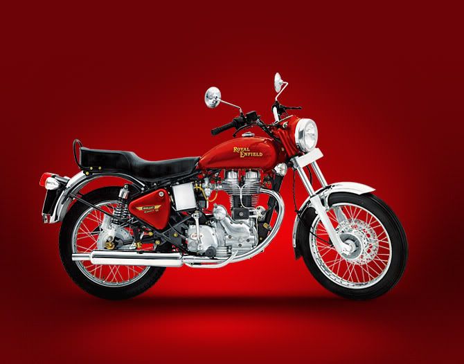
EnfieldMotorcycles.in is the blog for all Royal Enfield enthusiast where we live, breathe, and eat Royal Enfield Bullet . We not only keep you informed of the news about Royal Enfield originals, but also give custom bikes and historical bikes a lot of attention. You can also find with us the best Enfield related movies and crazy stunts etc. We are testing and reviewing new models of which a complete relief will be shown on our site. Finally, we have technical tips, for example, how to properly get engine through the winter.
Read more
Clutch and Primary Chain adjustments for royal enfield 350cc and 500cc cast iron engine
Friday, August 12, 2011
1. The Clutch - 350cc and 500 cc
The 350cc clutch has five driven plates and four driving plates, including the friction disc on the sprocket.
The 500cc clutch is similar to that of 350cc, except that there are six driven plates and five driving plates.
Also the lugs on the clutch sprocket and the splines on clutch centre are longer.
2.Removal of the Clutch
Remove the L.H. front foot rest, place a tray beneath the primary chain case to collect the oil in the chain case. Remove the central nut in the chain case outer and remove the cover.To remove the clutch unscrew the clutch spring pins. Lift away the spring caps, springs, clutch front plate, clutch pad in main shaft, the assembly of driving and driven clutch plates and the clutch retaining spring. The clutch sprocket can then be withdrawn along with the chain and engine sprockets (see point 10).
The clutch centre can be removed only after the engine sprocket, primary chain and the clutch sprocket have been removed.
To remove the clutch centre hold the clutch with a brake bar (Special tool No PED 2025) and remove the centre retaining nut and washer with a box spanner. The clutch centre can then be withdrawn from the shaft using extractor (Special Tool No. PED 2005).
3. Removal of Engine and Clutch sprockets
Remove the alternator stator by undoing three nuts. The primary chain is endless hence it is necessary to remove both the engine and clutch sprockets simultaneously.
Remove the central hexagon nut securing the alternator rotor, which can then be drawn off, taking care not to lose the key.
| |
4. Removal of Final Drive Sprocket
Remove the clutch as described above. Remove the primary chain tensioner.
Remove the primary chaincase inner by removing three nuts. Straighten the bent tab of the tab washer, which is provided for locking the final drive sprocket nut. Hold the sprocket and remove the nut (right hand thread). The sprocket can then be withdrawn. |
5. Re-assembly of the Clutch Plates
When re-assembling the clutch plates the following order must be observed.
The clutch pad must be fitted into the main drive shaft, plain dished plate (dish projecting outwards).
Friction plate with inserts, plain flat plate, friction plate bonded, plain dished plate (dish projecting inwards), friction plate bonded, clutch front plate, 3 springs on the clutch centre lugs.
In the case of 500cc one more plain flat plate will also have to be fixed after the plate with inserts has been assembled.
The other three springs are located by means of bosses on the clutch cap. Tighten the spring pins as far as they will go. If the clutch lifts un evenly it is probably is that one of the springs has taken a set in which case new springs should be fitted.
The friction plates with inserts should be renewed if badly worn or when the inserts have become loose in their plate. The bonded friction plates require renewal when worn or charred. ( A light change to blackish colour should not be mistaken as charred).
Excessive or premature wear of the plates is due to either running the vehicle at half clutch application or depriving clutch plates of oil, with insufficient or no oil in the clutch chain case.
6. Primary Chain Adjustments
Access to the primary chain adjuster is gained by removing the primary chain cover, which is held in position by a single nut. Before removing the nut, place a tray under the engine to collect the oil from the chaincase.
Beneath the bottom run of the chain is a curved slipper chain tensioner pad on which the chain rests. This can be raised or lowered by turning the adjusting screw below the chain tensioner pad after having first slackened the locknut.
The chain should be adjusted so that there is 1/4" up and down movement at the centre of the top run of the chain. Remember to check the chain. Remember to check the chain tension at 3 or 4 places and then adjust accordingly.
Ensure that the chain tensioner pad moves freely and the lock nut of the adjuster is retightened after carrying out the adjustments. The chain has to be changed if its length has increased by 3/4" more than the length of a new chain.
After replacing the chain cover remember to replenish the chaincase with oil (SAE 20) up to the level plug in outer chain case (approx quantity 430 to 450 ml)
Clutch Assembly 350 cc
| 1.Clutch center and back plate assembly | 12. Clutch intermediate plate (flat) |
| 2.Clutch sprocket 56 T & Drum assembly | 13. Clutch bonded plate assembly |
| 3.Clutch sprocket drum (N/S) | 14. Clutch front plate |
| 4.Clutch sprocket friction disc | 15. Clutch spring |
| 5.Clutch sprocket friction disc rivet | 16.Clutch Cap |
| 6.Clutch sprocket ball cage (N/S) | 17.Clutch spring screw |
| 7.Clutch sprocket ball cage rivets (N/S) | 18.Clutch pad |
| 8.Clutch sprocket balls(3/16" dia) (N/S) | 19. Clutch rod |
| 9.Clutch retaining spring | 20. Washer main shaft (spring) |
| 10.Clutch intermediate plate (dished) | 21. Nut main shaft (Nyloc) |
| 11.Clutch plate (insert type) |
Clutch Assembly 500 cc
| 1.Clutch center and back plate assembly | 12. Clutch intermediate plate (flat) |
| 2.Clutch sprocket 56 T & Drum assembly | 13. Clutch bonded plate assembly |
| 3.Clutch sprocket drum (N/S) | 14. Clutch front plate |
| 4.Clutch sprocket friction disc | 15. Clutch spring |
| 5.Clutch sprocket friction disc rivet | 16.Clutch Cap |
| 6.Clutch sprocket ball cage (N/S) | 17.Clutch spring screw |
| 7.Clutch sprocket ball cage rivets (N/S) | 18.Clutch pad |
| 8.Clutch sprocket balls(3/16" dia) (N/S) | 19. Clutch rod |
| 9.Clutch retaining spring | 20. Washer main shaft (spring) |
| 10.Clutch intermediate plate (dished) | 21. Nut main shaft (Nyloc) |
| 11.Clutch plate (insert type) |
7. Adjustment of the Clutch Control
It is essential that there should be about 3 to 4mm free movement in the clutch cable to ensure that all the spring pressure is exerted on the plates.
There are two points of adjustments on the clutch cable. The first is the midway adjuster at the middle of the cable just above the chain case. The adjustment is made by screwing the adjuster screw in or out of the adjuster body. Tighten the locknut on the screwed collar after adjustment has been made.
There are two points of adjustments on the clutch cable. The first is the midway adjuster at the middle of the cable just above the chain case. The adjustment is made by screwing the adjuster screw in or out of the adjuster body. Tighten the locknut on the screwed collar after adjustment has been made.
The other point is at the handlebar end. Loosen the locknut and thread in the adjuster to increase play and vice-versa to reduce play. Tighten lock nut after carrying out adjustment. However, if the adjusters have reached their maximum position, then the adjustment can be carried out in the gearbox outer cover. Before proceeding on the adjustment, turn in both cable adjusters to their fully closed position (fully in position).
Owing to initial bedding down of the clutch plate inserts, the clutch control may require adjustment after the first few hundred kms with a new machine. This point should therefore be examined soon after delivery and adjustment made if necessary. Initially, excessive play in the cable can be taken up through midway adjuster and the adjuster at the handle bar end.
NOTE: The clutch adjuster ball and clutch rod may require cleaning and greasing around 6000 miles / 10000 kms usage. To do this, loosen and carefully remove the clutch adjuster from its position, taking care not to drop it into the gearbox outer cover.
Start the engine and tilt the motorcycle towards the gearbox side, so that the clutch rod can be removed. Wash thoroughly, the clutch rod and adjuster and look for chipped or worn clutch rod ends and free rotation of the clutch adjuster ball.
Smear multipurpose grease on the clutch rod and carefully reassemble in its location. Adjust the adjuster to ensure free play is maintained on the handle bar end and tighten locknut.
Smear multipurpose grease on the clutch rod and carefully reassemble in its location. Adjust the adjuster to ensure free play is maintained on the handle bar end and tighten locknut.
Related Posts by categories
Show your Love for Royal Enfield !!

Cleaning your Royal Enfield
An exhaustive article about cleaning and maintaining your royal enfield !!

EFI Made Easy
Everything you need to know to take care of the system on your new EFI Royal Enfield in one short article.


very nicely written !!!
Posted on 1:08:00 AM
Post a Comment